AT-LP60X Headphone Mod
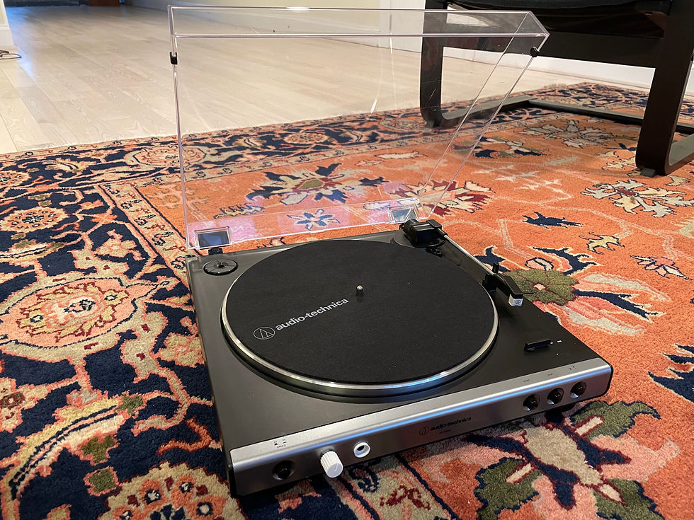


The Audio Technica AT-LP60X turntable doesn't have a headphone output. In this mod, I integrate a headphone amp and headphone jack into the turntable so that the listener can use headphones without an external amp.
Materials
Although I considered adding Bluetooth and even USB connectivity (for digitization), I decided to keep the project as simple as such for the sake of completing it.
The project has three main parts: power, amplification, and output. The power stage takes the 12 volts of the turntable's power supply, and converts it to the 5 volts which the amplifier uses. This is accomplished using LM2596S buck converter, trimmed to 5V. The amplification stage uses the MAX4410 headphone amplifier to convert the table's preamplified output to a headphone line level signal. The board also includes a potentiometer, which is desoldered and attached separately. It is used to adjust volume levels. Finally, my in-house 3.5 MM PCB is used to output audio to a pair of headphones.
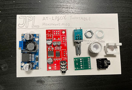
In addition to the three primary components, you will also need to 3D print a knob for the potentiometer, and a holder for the headphone jack.
The total cost ends up being between 30 and 40 USD, depending on how you source the headphone jack.
To complete this mod, you will need standard tools, along with a drill and bit set.
Steps
These instructions accompany the video. Please use both when completing this mod.
1. Disassembly
Remove the dust cover, felt mat, 45 RPM adapter, and metal disc, taking care of the belt. Place the dust cover upside down on a clean, soft surface, and then flip and place the turntable on top. Proceed by removing all visible screws. The bottom cover should slide out. Disconnect all the wire extensions, then remove buttons. Remove the foil shielding as well.
2. Soldering
Prepare 5 pieces of insulated wire about 10" in length. Solder three to the audio output jack and two to the power jack. Then desolder the potentiometer and JST connectors from the Amplifier Board.
3. Drill
Mark and drill a 1/2 inch hole and a 1/4 in hole in the front plate, and two matching holes in the frame. These will allow the headphone jack and potentiometer to fit. You may need to chamfer the potentiometer hole some to make it fit, due to the small allignment bump on its front
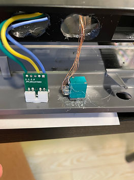
4. Wire
Assemble the 3.5 MM Jack by soldering the board together and then superglueing the board to the holder piece. Then, solder wires to the board and the respective output pins on the amplifier. Prepare pieces of Urethane Coated copper wire, and use those to connect the desoldered potentiometer back to its footprint on the amplifier board. Trim the buck converter to 5V using a 12V power source and a multimeter. Then, wire the power wires from the Turntable to the buck converter, and then wire the buck converter to the amplifier. Solder the audio output wires as well.
5. Assemble
Superglue the 3.5 MM jack into a hole on the front plate. Screw the potentiometer into its holes, and add the nut. Hot glue all the boards into free space inside the turntable. Reassemble the turntable in reverse, taking care to replace everything as it was before.